
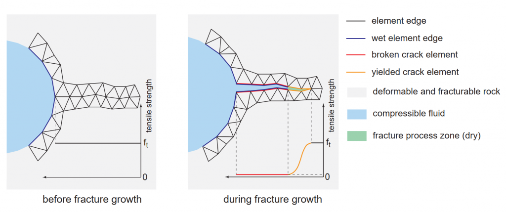
A new set of boundary conditions were implemented in Irazu version 6.1 to simulate the fluid-pressurization of a growing network of fractures that are connected to an initial, user-defined cavity (e.g., borehole). The motivation for the implementation of this type of boundary condition is to simulate the dynamic propagation of high-pressure compressible fluids into fractures generated from the blasting process. Practical applications where propagating boundary conditions can be used include: rock pre-conditioning for caving or stress-relief, rock fragmentation from blasting, in-situ recovery/leach mining, enhanced geothermal systems, and unconventional reservoirs.
The module is enabled in Project Options > Enable propagating boundary conditions and is currently only compatible with Mechanical simulations. When enabled, a Propagating Conditions tab is added with five propagating boundary condition types. Typically, the boundary condition is assigned to the boundary nodes of the initial cavity. Five Propagating Boundary Conditions types are available in Irazu:
- Pressure
- Pressure – adiabatic expansion
- Pressure – adiabatic expansion (linear flow)
- Flow rate
- No flow
A description of each boundary condition is provided in the following sections.
Pressure
The pressure boundary condition can be constant or time-varied. As fractures nucleate and grow throughout the simulation, and granted that they are connected to the initial cavity, the same pressure will be applied to the new fractures.
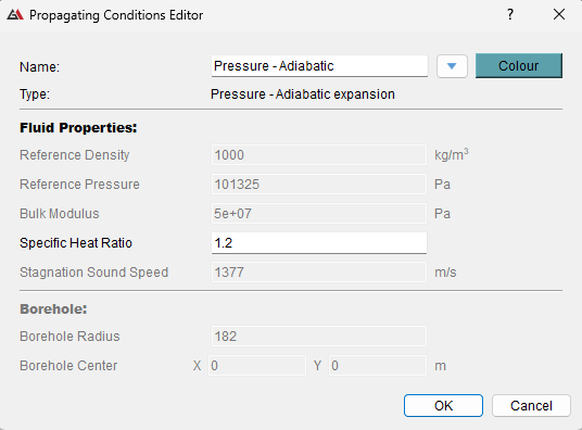
Pressure – adiabatic expansion
Adiabatic expansion pressure assumes an ideal gas pressure value that is either constant or time-varied. The ideal gas pressure is modified under the assumption of adiabatic ideal gas expansion and can be considered a scaled pressure value. The specific heat ratio (sometimes referred to as the isentropic expansion coefficient) of the gas needs to be specified for this boundary condition type. The model is two-way coupled in that the gas pressure is applied as an intra-crack boundary condition and the deformation of rock affects the cavity volume and therefore the gas pressure.
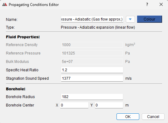
Pressure – adiabatic expansion (linear flow)
Adiabatic expansion pressure with gas flow approximation uses a simplified model of gas flow within the fractures initiating from the initial cavity. A pressure front is assumed to move radially from the borehole at sonic speed. It is assumed that the pressure at the cavity follows adiabatic gas expansion and is linearly varied to 0 at the pressure front. The specific heat ratio, stagnation sound speed, and borehole geometry should be specified for this boundary condition type.
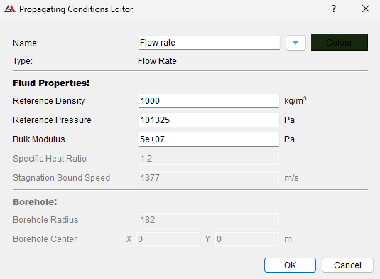
Flow rate
Using this condition, a constant or time-varied flow rate of a slightly compressible fluid is applied to the initial cavity. The pressure value applied to the initial cavity and all connected fractures to the initial cavity is calculated based on the principle of mass conservation for a slightly compressible fluid. The pressure will change as fluid is injected (increase in mass) and will also change with variations in cavity volume. Two-way coupling between the mechanical response of the rock and fluid pressure is achieved as variations in cavity volume due to rock deformation will affect the fluid pressure, which in turn affects rock deformation. The density and bulk modulus of the fluid, and the initial pressure applied to the cavity should be defined for this boundary condition type.
No flow
The no flow boundary condition type specifies nodes where fluid pressurization cannot propagate.