During hydraulic fracturing treatments from horizontal wells, proppant slurries are pumped into the induced fractures to prevent crack closure upon de-pressurization, thus enhancing hydrocarbon recovery. Transport and emplacement of proppant particles may have a strong influence on the rock mass stress re-distribution and hydraulic conductivity of the induced fracture network. Therefore, prediction of proppant injection performance can bring significant value to stimulation operations. Based on these considerations, a novel 2D/3D proppant logic was developed for the finite-discrete element method (FDEM) and implemented in Geomechanica’s Irazu software.
The proppant formulation accounts for a number of coupled processes, including:
- proppant slurry advection and gravity settling in fractured rock masses;
- concentration-dependent viscosity model;
- proppant convection;
- pack formation; and
- tip screen-out.
With this approach, the fluid flow equations are solved for a two-component slurry (i.e., fluid + proppant) and not for each individual component. The equation describing the movement of proppant concentration via the bulk flow of the carrying fluid (i.e., advection equation) is solved using an upwind integration scheme. As shown in Figure 1, coupling with the hydraulic solver occurs through the slurry density and slurry viscosity. Coupling with the mechanical solver occurs through the formation of proppant packs, which are represented as stiff intra-crack “spring” elements preventing fracture closure upon de-pressurization.
![]()
Figure 1. Explicit coupling between mechanical, hydraulic and proppant transport solvers implemented in Irazu.
The capabilities of the new proppant formulation are showcased by the 3D simulation of proppant transport and settling through an existing vertical fracture in an impermeable rock (Figure 2). The model geometry consists of a 1 m high, 10 m long fracture with uniform aperture. The fracture is first subjected to steady-state fluid flow conditions, then a constant proppant concentration of 0.3 is applied to the upstream side of the fracture. The (clean) fluid has viscosity and density values equal to 1e-3 Pa ⋅ s and 1,000 kg/m3, respectively; the diameter of the proppant particles is 0.2 mm; and a saturation concentration equal to 0.55 is assumed. Gravitational acceleration is oriented in the negative Z-direction.
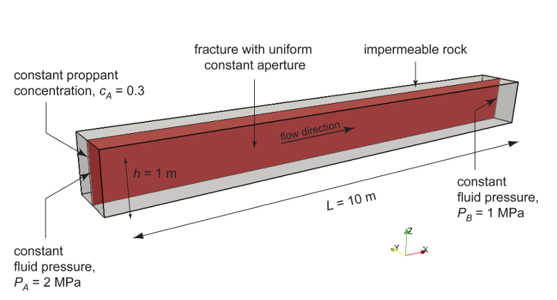
Figure 2. Geometry and boundary conditions of the proppant transport and settling simulation.
Simulation results are presented in terms of temporal evolution of proppant concentration and flow speed contours for two values of proppant specific gravity, SG = 2.1 (density = 2,100 kg/m3) and SG = 1.5 (density = 1,500 kg/m3) in Figure 4 and 5, respectively. Proppant is carried through the fracture by the movement of the base fluid. At the same time, however, it tends to settle under the effect of gravity (Stokes’ law) and to form a pack upon reaching the concentration saturation. The formation of a pack at the bottom of the fracture restricts the effective flow area through the fracture, thus causing a localized increase of flow speed. As expected, the higher density proppant has a faster settling rate in the carrier fluid and, for a given fluid viscosity, it penetrates less into the fracture compared to the lighter proppant.
Figure 3. Simulation results for Specific Gravity of proppant = 2.1.
Figure 4. Simulation results for Specific Gravity of proppant = 1.5.
The new proppant logic is fully integrated into the Irazu Graphical User Interface where proppant properties and boundary conditions can be readily assigned. The computational module will be made available in the upcoming release of the Irazu software. If you are interested in receiveing further information, please feel to contact us at info@geomechanica.com.