Measuring the strength and elastic moduli of rock using uniaxial compressive strength (UCS) testing is an important aspect of geotechnical investigations. The measured parameters include the peak strength, elastic modulus (E), and Poisson’s ratio (ν) which are among the key parameters used in any rock engineering project. To assess the E and ν, the test setup will need to be instrumented with strain measuring devices. The most used devices are strain gauges (SGs) and linear variable displacement transducers (LVDTs).
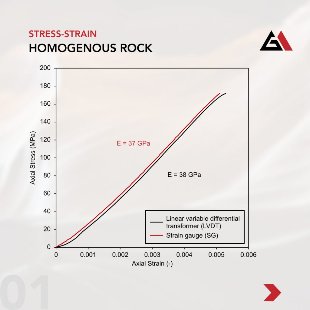
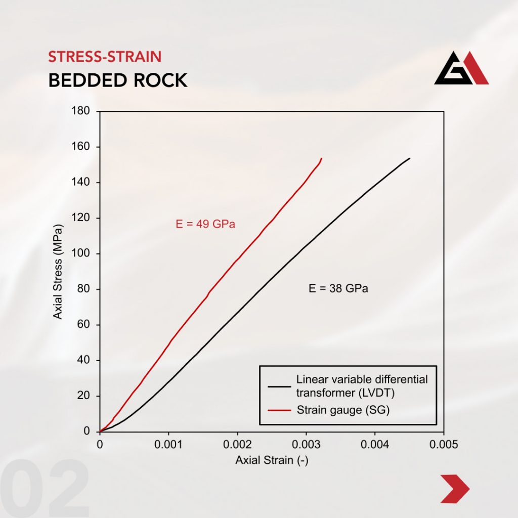
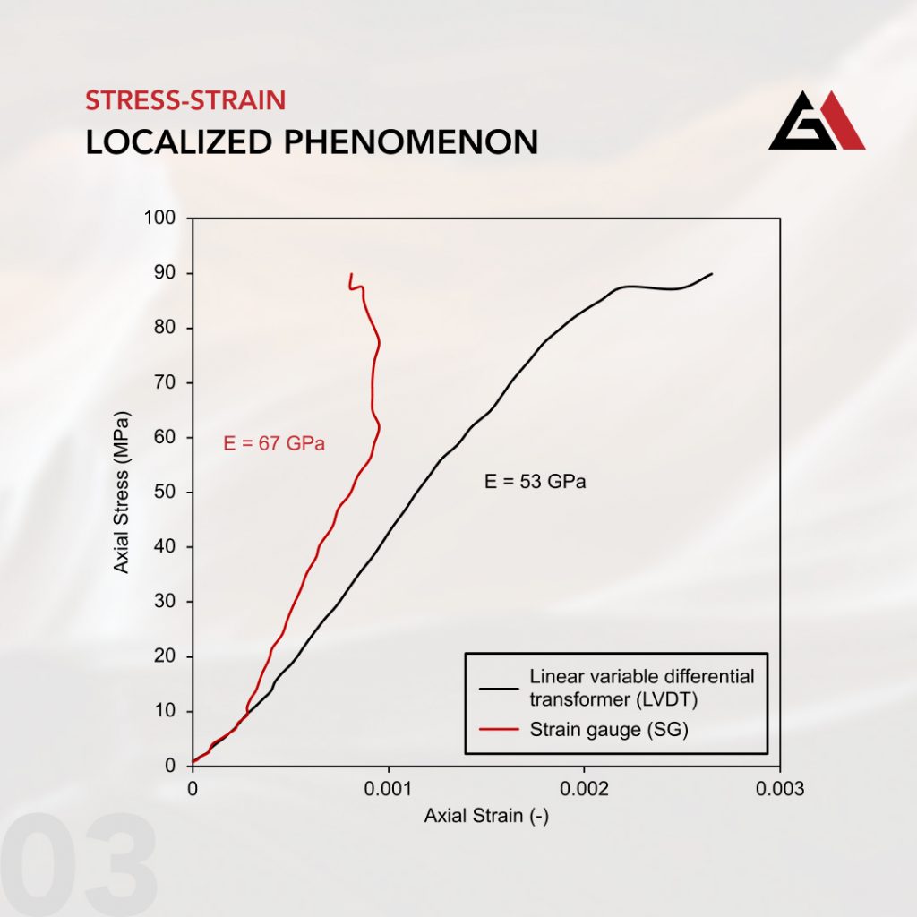
The key difference between SGs and LVDTs is the scale at which they measure strain. SGs measure strain over a small region located at the mid-height of the sample (i.e., localized measurement), while LVDTs measure over a larger region up to the entire length of the sample. SGs are directly bonded with an adhesive to the sample, while LVDTs are affixed to the loading platens. These differences may lead to contrasting strain measurements depending on the rock type being tested and the localized behaviour of the test specimen where the SG is affixed. This potential contrast is demonstrated using three experimental examples where both SGs and LVDTs were used to measure sample strain. In these examples, the average E (i.e., linear least squares fit) was calculated using data from 50% ± 5% of the peak strength and the apparatus deformation was subtracted for the LVDT strain to only consider the sample strain (For further information on this procedure, please see our previous post on UCS compliance).


In the first example (Image 1) of a UCS test conducted on a fairly homogenous rock, the E calculated using either strain measuring device is similar. In the second example (Image 2) of a UCS test conducted on a layered rock with layers of varying stiffness, the E calculated from the SG is stiffer than that based on LVDTs. The measured LVDT strain is greater because it captures all the low joint stiffness bedding planes within the sample that are located above and/or below the SG locations. In the last example (Image 3), of a UCS test conducted on a layered rock with layers of varying stiffness or flaws, the SG measurements deviate from LVDT measurements as a result of the SGs partially debonding from the specimen surface due to excessive localized strain.
These examples demonstrate that the choice of strain measurement device may result in significantly different elastic parameters. In using any of these measured parameters in design or analysis, one should be aware of these potential differences. More specifically, we need to be able to scrutinize test results to understand what is truly being measured before blindly adopting the resulting parameters. There may be advantages to each strain measurement approach in different situations. We will leave the topic of the preferred strain measurement approach for different rock types for further discussion in the future.
